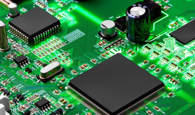
What is a Printed Circuit Board (PCB)?
Joe Howard -Nomenclature Once the soldermask layers are finished, figuring out records, marks and from time to time bar codes, are published onto the soldermask. These marks are known as nomenclature, and they will additionally be described by means of files that had been protected with the alternative gerber layers. They are published onto the solder mask to help guarantee accurate meeting of the PCB.

Printed Circuit Board Design PCBs are available a ramification of designs, so it is essential to have a radical information of the layout technique. Rigid PCB Some of the important thing factors to remember when designing a PCB include:
Application for which the PCB might be used Environment wherein the PCB will function Amount of space and configuration required for set up Flexibility of the PCB Installation and meeting Selecting the right PCB layout to healthy these concerns appreciably affects manufacturability, production pace, product yield, operation fees, and lead instances.
For greater insights into the design system – specially for inflexible flex systems, which we describe further down this web page – down load our free Rigid-Flex PCB Application & Design Guide.
We have additionally acquired UL ninety four V-zero qualification for rigid-flex and flexible circuits, with the most important list of UL rankings for rigid flex international. So, your forums can be ninety four V-zero certified with out additional testing (accordingly expediting the fabrication and delivery of our PCBs). For greater records at the significance of UL qualification for rigid-flex PCBs, see our white paper “The Problem With UL Approval of Rigid-Flex Circuits”.
Printed Circuit Board Fabrication The creation and fabrication of PCBs include the subsequent steps:
Chemically imaging and etching the copper layers with pathways to connect digital additives
Laminating the layers together, using an bonding fabric, that also acts as electrical insulation, to create the PCB Drilling and plating the holes inside the PCB to attach all of the layers collectively electrically
Imaging and plating the circuits on the outside layers of the board Coating each aspects of the board with soldermask and printing the nomenclature markings at the PCB The boards are then machined to the scale which can be in the fashion designer’s perimeter gerber file
Once complete, the PCB board is ready for additives to be assembled to it. Most normally the additives are attached to the PCB by means of soldering the components immediately onto exposed lines – called pads – and holes inside the PCB. Soldering may be achieved by hand, but greater commonly is done in very excessive-pace automated meeting machines.
Two of the maximum common PCB meeting techniques are surface-mount device (SMD) or thru-hole technology (THT). The use of both relies upon on the size of the components and the configuration of the PCB. SMD is beneficial for at once mounting small additives on the outside of the PCB, even as THT is right for mounting huge components through massive pre-drilled holes within the board.
Archives
- January 2026
- December 2025
- November 2025
- October 2025
- September 2025
- August 2025
- July 2025
- June 2025
- May 2025
- April 2025
- March 2025
- February 2025
- January 2025
- December 2024
- March 2024
- February 2024
- January 2024
- December 2023
- November 2023
- October 2023
- September 2023
- August 2023
- July 2023
- June 2023
- May 2023
- April 2023
- March 2023
- February 2023
- January 2023
- December 2022
- November 2022
- October 2022
- September 2022
- August 2022
- July 2022
- June 2022
- May 2022
- April 2022
- March 2022
- February 2022
- January 2022